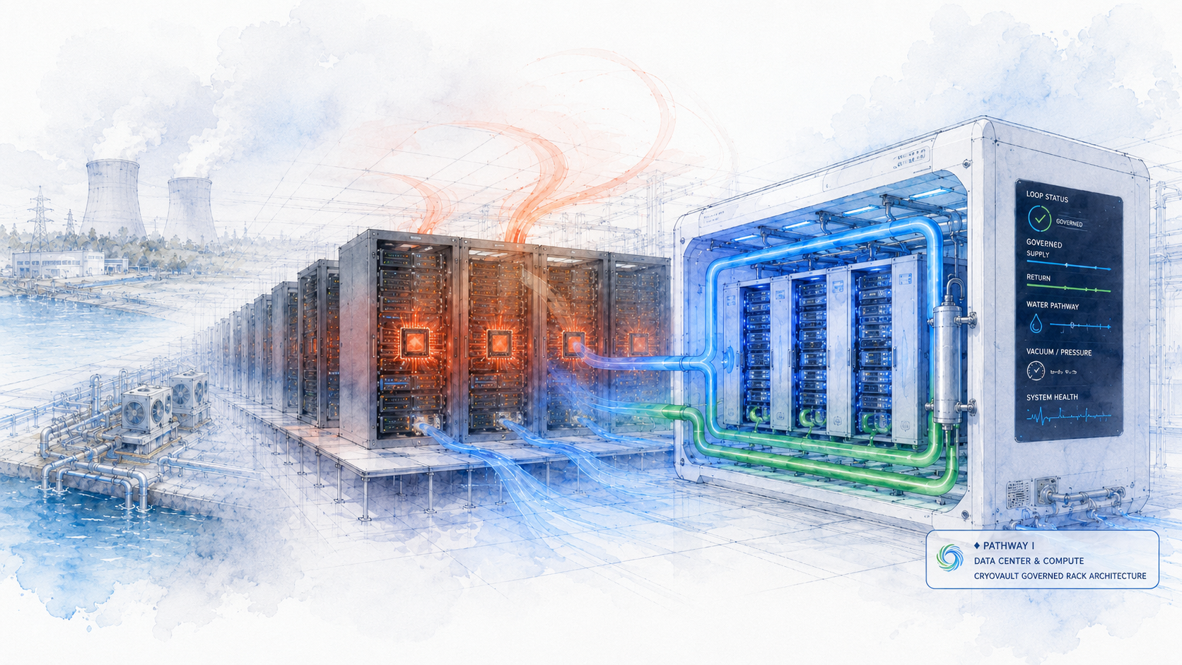
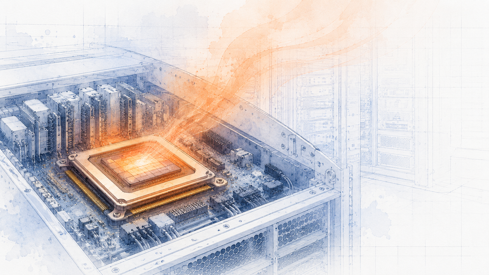
The first thermal burden is not the building. It is the compute device. In conventional architecture, heat escapes the chip, enters the rack, enters the aisle, and becomes a building-scale emergency before any governance architecture ever touches it.
| Conventional Compute Burden | Representative Anchor |
|---|---|
| H100 PCIe GPU -- max TDP | 350 W per GPU |
| DGX H100/H200 system heat output | 38,557 BTU/hr |
| Required airflow at 80% fan PWM | 1,105 CFM front-to-back |
| Operating temperature range | 5 degrees C to 30 degrees C |
Source: NVIDIA DGX H100/H200 User Guide; NVIDIA H100 PCIe Product Brief.
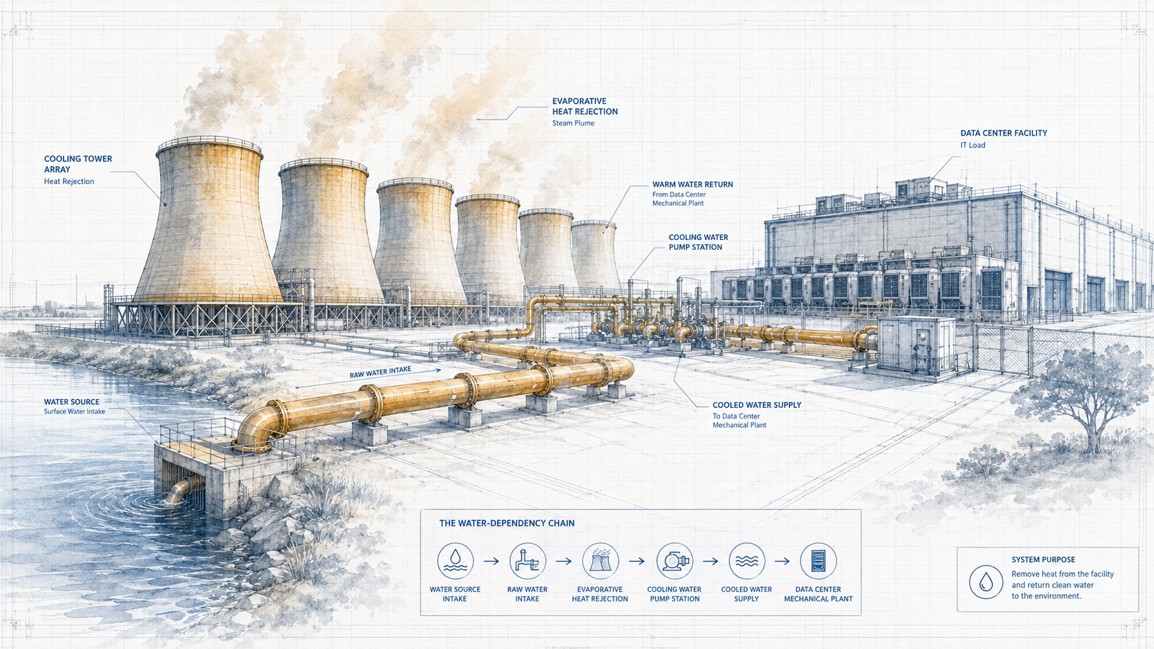
Many data centers do not only consume power. They consume community water to reject heat. Cooling architecture has become a water policy issue in regions where data center density is growing fastest.
| Water Impact | Representative Anchor |
|---|---|
| Medium-sized data center -- cooling water use | Up to approximately 110 million gallons per year |
| Large data center -- peak water use | Up to 5 million gallons per day in some cases |
| Indirect water impact | Electricity generation also carries water cost through grid mix |
Source: Environmental and Energy Study Institute (EESI), 2025; Lawrence Berkeley National Laboratory 2024 U.S. Data Center Energy Report.
CryoFlux targets a zero evaporative process water pathway for CryoVault module deployments. This is framed as a design-intent target for the governed enclosure architecture, not a universal claim for every installation.
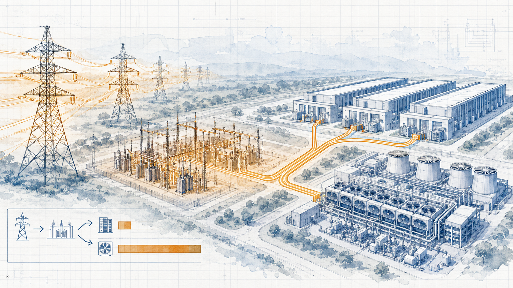
PUE tells the story plainly: a data center is not only buying compute power. It is buying the overhead required to remove compute heat. A PUE of 1.58 means that for every watt delivered to compute, an additional 0.58 watts are consumed to manage what that compute watt left behind.
| Facility Efficiency Metric | Representative Anchor |
|---|---|
| Industry average PUE, 2023 | 1.58 |
| Industry PUE range since 2020 | Approximately 1.55 to 1.59 |
| Large data centers (20 MW+) global average PUE, 2025 | 1.44 |
Source: Uptime Institute 2023 and 2025 Global Data Center Survey.
CryoFlux targets a lower overhead architecture by reducing the distance between thermal burden, cold delivery, return capture, and governed-state verification. Specific PUE improvement figures will be reported from pilot and prototype data.
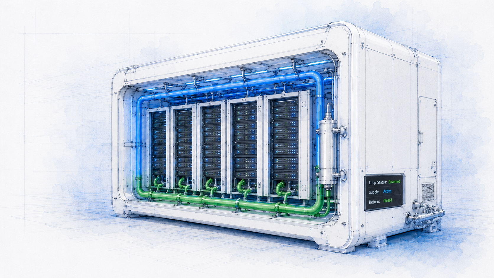
CryoFlux does not merely cool the room. It establishes a governed cold domain around the workload -- delivering LN2 as a precision-governed thermal asset through a closed loop, instrumenting the state, capturing the return, and renewing the cold for reuse.
| CryoVault Design Target | Intended Commercial Meaning |
|---|---|
| Atmospherically evacuated enclosure | Reduce convective heat transfer and moisture/condensation risk at the compute environment boundary |
| Governed cryogenic delivery loop | Deliver cold as architecture -- precision LN2 supply to the thermal burden source, not ambient room air conditioning |
| Instrumented state reporting | Temperature, pressure/vacuum, flow rate, return state, and loop health telemetry -- continuously monitored |
| Zero evaporative water pathway | Reduce or eliminate cooling tower dependency for the governed enclosure module |
| No high-GWP refrigerant HVAC dependency | Reduce exposure to HFC phase-down regulation and refrigerant leakage risk. LN2 is inert, non-toxic, 78% of atmosphere. |
| Thermal burden captured closer to source | Move from ambient rejection after heat escapes to governed recovery at or near the compute device |
Refrigerant regulatory context: EPA regulations effective January 1, 2025 restrict certain high-GWP HFC applications. EPA -- Technology Transitions HFC Restrictions by Sector.
The CryoCycler regeneration loop converts LN2 from a consumable supply-chain material into a governed, reusable thermal asset. Cold is delivered, burden is absorbed, the loop closes, and the cold is renewed -- not discarded.
CryoVacuLock / CryoVestibule architecture maintains the atmospheric boundary of the governed compute enclosure -- controlling moisture, preventing condensation flash-freeze events, and sustaining the low-pressure cryogenic environment at the thermal interface.
CTD geometry at the thermal interface governs the flow redistribution, cross-channel dynamics, and contact architecture at the point of burden. Cold is delivered where the burden originates -- not managed after it escapes.
| Category | Conventional Data Center Cooling | CryoFlux Governed Cold-Domain Approach |
|---|---|---|
| Thermal control point | Room / aisle / rack after heat has already escaped the compute source | Closer to the compute source and enclosure state -- governed before propagation |
| Cooling mechanism | Air movement, chillers, CRAC/CRAH units, cooling towers, pumps, refrigerant loops | Cryogenic LN2 delivery loop, return capture, instrumented cold-domain state |
| Working medium | HFC/HFO refrigerants -- regulated, high GWP in legacy systems, subject to EPA phase-down | Liquid nitrogen -- inert, non-toxic, 78% of atmosphere, no high-GWP regulatory exposure |
| Water dependency | Often significant where evaporative cooling towers are used -- up to millions of gallons per day for large facilities | Design target: zero evaporative process water for CryoVault module -- no cooling tower required |
| Grid overhead (PUE) | Industry average 1.58 in 2023 -- meaning 58 cents of overhead per dollar of compute power | Lower overhead architecture targeted by reducing dependency on mechanical cooling plant -- pilot data pending |
| Failure mode | Hotspots, fan load, airflow imbalance, refrigerant/water/grid dependency chains | Governed state telemetry: pressure, temperature, flow, return, and loop health continuously reported |
| Commercial model | Manage heat as facility overhead after it escapes the compute source | Govern heat as architecture -- deliver cold to the burden, capture the return, renew the loop |
Conventional HVAC/chiller systems depend on HFC refrigerants with Global Warming Potentials hundreds to thousands of times greater than CO2. EPA regulations effective January 1, 2025 restrict certain HFC applications. CryoFlux replaces the refrigerant dependency chain with liquid nitrogen -- inert, non-toxic, and constituting 78% of the atmosphere. No phasedown risk. No leakage liability.
Medium-sized conventional data centers can consume up to approximately 110 million gallons of water per year for cooling. Large facilities may exceed 5 million gallons per day. CryoFlux CryoVault architecture targets zero evaporative process water consumption for the governed enclosure module -- returning that resource to the community water supply and reducing the environmental footprint of compute infrastructure.
The conventional data center cooling plant -- fans, chillers, pumps, towers, compressors -- consumes a significant fraction of total facility power. CryoFlux targets a lower mechanical overhead architecture by delivering cold through a governed loop rather than operating a building-scale air and water rejection system. Specific efficiency improvements will be reported from pilot program data.
CryoFlux asks the architecture to govern it.